ENGINEERING METHOD
Critical lines are analyzed for sustained, expansion, occasional, wind/seismic and equipment-nozzle cases; support strategy and spring/restraint requirements are developed iteratively with layout.

Converts P&IDs and line classes into constructible 3D routing while controlling flexibility, loads, vibration, supports and maintainability.
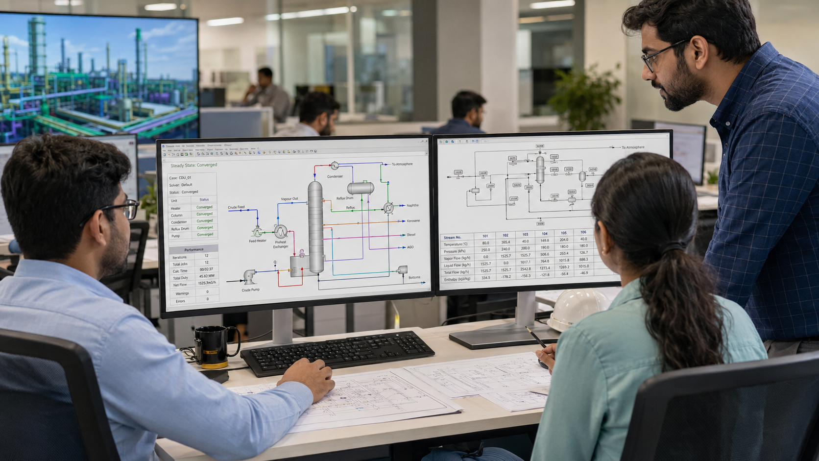
Critical lines are analyzed for sustained, expansion, occasional, wind/seismic and equipment-nozzle cases; support strategy and spring/restraint requirements are developed iteratively with layout.
Typical tools include CAESAR II-class stress analysis plus 3D plant-design and support-design applications.
Line list/class, operating/design cases, equipment nozzle allowables, routing, site loads, support constraints and dynamic/vibration concerns.
Piping layouts, stress reports, support loads/details, isometrics, MTO, tie-in packages, test limits and construction notes.
Model/isometric consistency, code-stress review, nozzle-load verification, support walkdown and as-built reconciliation.
High-temperature, cryogenic, rotating-equipment, relief/flare, two-phase and other critical process piping.
ASME B31.3 or EN 13480/DIN; applicable GOST piping standards by project. Software is selected per project scope, client requirement, interoperability and licensed availability; naming a tool class does not imply that every project uses every product.
ASME B31.3 or EN 13480/DIN; applicable GOST piping standards by project. Software is selected per project scope, client requirement, interoperability and licensed availability; naming a tool class does not imply that every project uses every product.